Young's Modulus by Searle's Method
Contents
- Introduction
- IIT JEE Solved Problems | 2014 | 2012 | 2007 | 2004 | 2003
- Measurement of Young's Modulus by Searle's Apparatus
- Stress Strain Curve
- Exercise Problems
- References
Introduction
Any solid material undergoes some elastic deformation if we apply a small external force on it. It is very important to know the extent of this deformation. Whenever, engineers design bridges or buildings and structural implants for body, it is useful to know the limits of elastic deformation for endurance.
Young's modulus is a measure of the stiffness of a solid material. It is calculated only for small amounts of elongation or compression which are reversible and do not cause permanent deformation when the external applied force is removed. For this reason, it is also called elastic modulus.
A stiff material has a high Young's modulus and changes its shape only slightly under elastic loads. A flexible material has a low Young's modulus and changes its shape considerably e.g. Young's modulus of steel is much more than rubber. So contrary to our perception, steel is considered more elastic than rubber. Young's modulus is a characteristic property of the material and is independent of the its dimensions i.e., its length, diameter etc. However, its value depends on ambient temperature and pressure.
Consider a wire of length L and diameter d. Let its length L increases by an amount l when the wire is pulled by a longitudinal external force F. Young's modulus of the material of the wire is the ratio of longitudinal stress to the longitudinal strain i.e., $$ Y=\frac{F/A}{l/L}=\frac{4FL}{\pi d^2 l} $$ The units of Young's modulus are the same as that of stress (note that strain is dimensionless) which is same as the units of pressure i.e., Pa or N/m2. Graphically, Young's modulus is generally determined from the slope of stress-strain curve.

Normally, we use Searle's method to measure the Young's modulus of a material. As Young's modulus is independent of the shape of the material, we can utilize any shape for its calculation. In particular, a thin circular wire fulfills our requirement. In this method, the length L of the wire is measured by a scale, diameter d of the wire is measured by a screw gauge, length l of the wire is measured by a Micrometer or Vernier scale, and F is specified external force.
Differentiate the expression for Y to get the relative error in the measured value of Y, $$ \frac{\Delta Y}{Y}=\frac{\Delta L}{L}+2\frac{\Delta d}{d}+\frac{\Delta l}{l} $$ where $\Delta L$, $\Delta d$, and $\Delta l$ are the errors in the measurement of $L$, $d$ and $l$, respectively. Generally, accuracy of these errors measurements depends on the least count of the measuring instrument.
Searle's method is quite popular in IIT JEE because it tests you on (1) measurement using the screw gauge and the Micrometer/Vernier scale and (2) measurement error analysis. Let us solve some IIT-JEE problems which are based on it.
IIT JEE Solved Problems
Problem from IIT JEE 2014
During Searle's experiment, zero of the Vernier scale lies between
3
Solution: The difference between two measurements by Vernier scale gives
elongation of the wire caused by additional load of 2 kg. In first measurement,
main scale reading is MSR = 3
In second measurement, MSR = $3.20\times 10^{-2}$ m and VSR = 45. Thus, second measurement by Vernier scale is, \begin{align} L_2 &=3.20\times 10^{-2}+ 45(1\times 10^{-5}) \nonumber\\ &=3.245\times 10^{-2}\;\mathrm{m} \end{align} The elongation of the wire due to force F = 2 g is, \begin{align} l=L_2-L_1=0.025\times10^{-2}\;\mathrm{m} \end{align} The maximum error in measurement of $l$ is $\Delta l=\mathrm{LC}=1\times 10^{-5}$ m. Young's modulus is given by $Y=FL/lA$. The maximum percentage error in measurement of $Y$ is \begin{align} \frac{\Delta Y}{Y}=\frac{\Delta l}{l}=0.04=4\%. \end{align}
Problem from IIT JEE 2012
In the determination of Young's modulus ($Y=\frac{4MLg}{\pi l d^2}$) by using Searle's method, a wire of length L = 2 m and diameter d = 0.5 mm is used. For a load M = 2 kg, an extension l = 0.25 mm in the length of wire is observed. Quantities d and l are measured using screw gauge and micrometer, respectively. They have same pitch of 0.5 mm. The number of divisions on their circular scale is 100. The contributions to the maximum probable error of the Y measurement,
- due to the error in the measurements of d and l are the same.
- due to the error in the measurement of d is twice that due to the error in the measurement of l.
- due to the error in the measurement of l is twice that due to the error in the measurement of d.
- due to the error in the measurement of d is four times that due to the error in measurement of l.
Solution: Differentiate given expression of Y and then divide by Y to get, \begin{align} \frac{\Delta Y}{Y}=\frac{\Delta l}{l}+2\frac{\Delta d}{d}. \end{align} From given data, the least counts of screw gauge and micrometer are pitch divided by number of divisions on the circular scale i.e., 0.5/100 = 0.005 m. Hence, $\Delta d=\Delta l=0.005$ m. The equation gives error contribution to measured Y from error in $d$ as, \begin{align} e_d=2\frac{\Delta d}{d}=0.02, \end{align} and that due to error in $l$ as, \begin{align} e_l=2\frac{\Delta l}{l}=0.02. \end{align}
Problem from IIT JEE 2007
A student performs an experiment to determine the Young's modulus of a wire, exactly 2 m long, by Searle's method. In a particular reading, the student measures the extension in the length of the wire to be 0.8 mm with an uncertainty of $\pm 0.05$ mm at a load of exactly 1.0 kg. The student also measures the diameter of the wire to be 0.4 mm with an uncertainty of $\pm 0.01$ mm. Take g = 9.8 m/s2 (exact). The Young's modulus obtained from the reading is,
- $(2.0\pm 0.3)\times 10^{11}$ N/m2
- $(2.0\pm 0.2)\times 10^{11}$ N/m2
- $(2.0\pm 0.1)\times 10^{11}$ N/m2
- $(2.0\pm 0.05)\times 10^{11}$ N/m2
Solution: Young's modulus of wire material is given by, \begin{align} Y=\frac{\mathrm{stress}}{\mathrm{strain}}=\frac{4FL}{\pi d^2 l}. \end{align} From given data, $F=mg=9.8$ N, $L=2.0$ m, $l=0.8\times 10^{-3} $ m and $d=0.4\times10^{-3}$ m. Substitute the values to get $Y=1.95\times10^{11}\approx 2.0\times10^{11}$ N/m2.
Differentiate the expression for $Y$ and simplify to get error in $Y$, \begin{align} \frac{\Delta Y}{Y}=2\frac{\Delta d}{d} + \frac{\Delta l}{l}. \end{align} Substitute $\Delta d=0.01$ mm and $\Delta l=0.05$ mm to get $\Delta Y=0.1125Y\approx0.2\times10^{11}$ N/m2.
Problem from IIT JEE 2004
In a Searle's experiment, the diameter of the wire as measured by a screw gauge of least count 0.001 cm is 0.050 cm. The length, measured by a scale of least count of 0.1 cm, is 110.0 cm. When a weight of 50 N is suspended from the wire, the extension is measured to be 0.125 cm by a micrometer of least count 0.001 cm. Find the maximum error in the measurement of Young's modulus of the material of wire from these data.
Solution: Young's modulus is given by \begin{align} Y&=\frac{4Fl}{\pi d^2 l}\nonumber\\ &=\frac{4(50)110.0}{3.14(0.050)^2(0.125)} \nonumber\\ &=2.24\times10^7\; \mathrm{N/cm^2}\\ &=2.24\times10^{11}\; \mathrm{N/m^2} \end{align}
Differentiate the expression for $Y$ and simplify to get, \begin{align} \frac{\Delta Y}{Y}&=\frac{\Delta L}{L}+2\frac{\Delta d}{d}+\frac{\Delta l}{l}\nonumber\\ &=\frac{0.1}{110.0}+2\frac{0.001}{0.050}+\frac{0.001}{0.125} \\ &=0.049. \end{align} Thus,$\Delta Y=1.09\times10^{10}$ N/m2.
Problem from IIT JEE 2003
The adjacent graph shows the extension ($\Delta l$) of a wire of length 1 m suspended from the top of a roof at one end and with a load W connected to the other end. If the cross-sectional area of the wire is 10-6 m2 calculate, from the graph, the Young's modulus of the material of the wire.

- 2× 10¹¹ N/m2
- 2× 10-11 N/m2
- 2× 10¹² N/m2
- 2× 10-12 N/m2
Solution: Young's modulus is defined as $Y=\frac{W/A}{\Delta l/L}$. Given, the cross-section area of the wire $A=10^{-6}$ m2 and the length of the wire L = 1 m. From the given graph, elongation of the wire is $\Delta l=10^{-4}$ m at load of W = 20 N. Substitute the values to get \begin{align} Y=\frac{20/10^{-6}}{10^{-4}/1}=2\times10^{11}\,\mathrm{N/m^2}. \end{align}
Measurement of Young's Modulus by Searle's Apparatus
Searle's Apparatus
It consists of two wires (control or reference wire and test wire) of equal lengths and are attached to a rigid support (see figure). Both control and test wires are connected to a horizontal bar at the other ends. A spirit level is mounted on this horizontal bar. Now, this bar is hinged to the control wire. If we increase the weight on the side of test wire, it gets extended and causes the spirit level to tilt by a small amount. We can adjust any tilt of the spirit level by turning the screw of a micrometer, which is positioned on the test wire side. We restore it to the horizontal position to take the desired readings.
In a variation of Searle's apparatus, the control wire supports a vernier scale which will measure the extension of the test wire. The force on the test wire can be varied using the slotted masses.

The micrometer is same as screw gauge. It has a main scale (shown vertically in the figure) and a circular scale (shown horizontally in the figure). When the screw is rotated to make the spirit level horizontal, the readings of the main scale and circular scale change. These readings are used to find the elongation l of the test wire.
Test Procedure
The test procedure is given below,- Measure the initial length L of the wire by using a meter scale.
- Measure the diameter d of the wire by using a screw gauge. The diameter should be measured at several different points along the wire.
- Adjust the spirit level so that it is in the horizontal position by turning the micrometer. Record the micrometer reading to use it as the reference reading.
- Load the test wire with a further weight. The spirit level tilts due to elongation of the test wire.
- Adjust the micrometer screw to restore the spirit level into the horizontal position. Subtract the first micrometer reading from the second micrometer reading to obtain the extension l of the test wire.
- Calculate stress and strain from the formulae.
- Repeat above steps by increasing load on the test wire to obtain more values of stresses and strains.
- Plot the above values on stress-strain graph; it should be a straight line. Determine the value of the slope Y.
Measurements
The wire may not be uniform or cross-section may not be exactly circular throughout the length of the wire. To avoid consequent error in the measurement of diameter, the screw-gauge reading is to be taken at different places and at mutually perpendicular directions at each place of the wire. Take mean value of these reading to get the average diameter.
In one set of measurements, measure the elongation by increasing the test weight from the minimum value to the maximum value (loading) and in another set, measure the elongation by decreasing the test weight from the maximum value to the minimum value (unloading), in same number of steps. This helps in checking repeatability of the measurements. It also help in checking whether elastic limit is exceeded. Take the mean value of measurement during loading and unloading to avoid error due to hysteresis effect. The measurements may be recorded in tabular format.
Results
Plot the calculated values of stress and strain on the stress-strain curve. Estimate the slope of this curve in the linear region to get the Young's modulus of the material of the wire.
You can also use the measured data to plot the load (F = Mg) versus extension l curve. This curve should be a straight line passing through the origin (see figure). The slope of this line gives $\tan\theta=l/F=l/Mg$. Substitute $l/F$ in the expression of Young's modulus to get

Substitute the measured value of L, measured value of d and estimated value of $\tan\theta$ (from graph) to get Young's modulus.
Points to ponder
- Will there be any error if the control (or reference) wire and the test wire are not of the same material? If wires are of different material then their thermal expansion (due to temperature change during experiment) will be different. This will introduce an error in the measured elongation l.
- The wires used in the experiment are identical, long and thin. The long and thin wires gives larger elongation and hence better measurement accuracy.
- The wires should be taut otherwise length L can not be measured correctly. The control weight or dead weight is used to make the wires taut.
- List out various sources of errors and ways to reduce them.
- When a set of readings are taken, the micrometer screw must be rotated in the same direction to avoid back-lash error. The micrometers (screw gauges) usually have back-lash error. It is the maximum change in micrometer reading to start physical movement of the screw in reverse direction. You can experience this error with a simple nut and bolt.
- After adding a load or removing a load, wait for some time before taking the next reading; this will help the wire to elongate or contract fully.
Stress Strain Curve
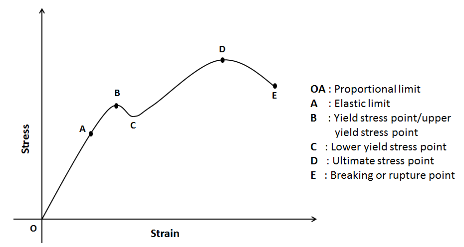
The stress-strain curve of a material indicates important mechanical properties of the material. The curve for a typical elastic material like metal wire is shown in the figure. Hooke's law, F = kl, is obeyed in the region of proportionality (region OA in the figure). The slope of the line OA gives Young's modulus Y. If the strain is increased beyond A, the stress is no longer proportional to the strain.
Can you answer why stress-strain curve is preferred over load-elongation curve? Refer your Physics textbook for more explanation on stress-strain curve.
Exercise Problems
- What do you understand by the statement "The elastic limit of steel is greater than that of rubber"?
- Refer to the stress-strain curve given in the Stress-Strain Curve
section. The wire behaves as a liquid in the part (CPMT 1988)
- AB
- BC
- CD
- OA
- The Young's modulus of a wire of diameter d and length L is Y. If the diameter and length are changed to 2d and L/2, respectively, then its Young's modulus will be?
- The ratio of radius of two wires of the same material is 2:1. If the same force is applied to both of them, the extension produced is in the ratio 2:3. What will be the ratio of their lengths?
-
The diagram shows a force-extension graph for a rubber band.
Consider the following statements
- It will be easier to compress this rubber than expand it
- Rubber does not return to its original length after it is stretched
- The rubber band will get heated if it is stretched and released
- 3 only
- 2 and 3
- 1 and 3
- 1 only
- A load of 4 kg is suspended from a ceiling through a steel wire of length 20 m and radius 2.0 mm. It is found that the length of the wire increases by 0.031 mm as equilibrium is achieved. Find Young's modulus of steel. Take $g=3.1\pi$ m/s2.
- The stress versus strain graphs for wires of two materials A and B
are as shown in the figure. If YA and YB are the Young's modulii of the materials,
then (Kerala (Engg.) 2001)

- YB = 2 YA
- YB = YA
- YB = 3 YA
- YA = 2 YB
-
The diagram shows the change x in the length of a thin uniform
wire caused by the application of stress F at two different temperatures T1 and
T2. The variations shown suggest that (CPMT
1988)

- T1 > T2
- T1 < T2
- T1 = T2
- none of these
- One end of a wire 2 m long and 0.2 cm2 in cross section is fixed in a ceiling and a load of 4.8 kg is attached to the free end. Find the extension of the wire. Young's modulus of steel is 2.0×10¹² N/m2.
-
The load versus elongation graph for four wires of the same
material is shown in the figure. The thickest wire is represented by the line (KCET 2001)

- OD
- OC
- OB
- OA
-
Two wires of equal cross section but one made of steel and the
other of copper, are joined end to end. When the combination is kept under
tension, the elongations in the two wires are found to be equal. Find the ratio of
the lengths of the two wires. Young modulus of steel is 2
. 0× 1011 N∕ m2 and that of copper is 1. 1× 10¹¹ N∕ m2 . - The ratio stress/strain remains constant for small deformation of a metal wire. When the deformation is made larger, will this ratio increase or decrease?
-
When a wire of length L is stretched with a tension F, it extend
by l. If the elastic limit is not exceeded, the amount of energy stored in the wire
is (IIT JEE 1990)
- Fl
- Fl/2
- Fl2/L
- Fl2/2L
-
The graph shows the behaviour of a length of wire in the region
for which the substance obeys Hooke's law. P and Q represent (AMU 2001)

- P = applied force, Q = extension
- P = extension, Q = applied force
- P = extension, Q = stored elastic energy
- P = stored elastic energy, Q = extension
-
A wire of length L and cross-sectional area A is made of material
of Young's modulus Y. The work done in stretching the wire by an amount x is
given by
- YAx2/L
- YAx2/2L
- YAL2/x
- YAL2/2x
-
The equivalent of spring constant k for a wire of length L, cross-sectional area A and Young's modulus Y is
- YL/A
- YA/L
- AL/Y
- YAL
-
A heavy uniform rod is hanging vertically from a fixed support. It
is stretched by its own weight. The diameter of the rod is
- smallest at the top and gradually increases down the rod
- largest at the top and gradually increases down the rod
- uniform everywhere
- maximum in the middle
-
The length of a metal wire is l1 when the tension in it
is T1 and is l2 when the tension is T2. The natural length of the wire
is
- $(l_1+l_2)/2$
- $\sqrt{l_1 l_2}$
- $(l_1T_2-l_2T_1)/ (T_2-T_1)$
- $(l_1T_2+l_2T_1)/ (T_2+T_1)$
-
A student plots a graph from his readings on the determination of
Young modulus of a metal wire but forgets to put the labels (see figure). The
quantities on x and y-axes may be respectively

- weight hung and length increased
- stress applied and length increased
- stress applied and strain developed
- length increased and the weight hung
-
The two wires shown in the figure are made of the same material
which has a breaking stress of 8&\times108 N/m2.The area of cross section of the upper
wire is 0.006 cm2 and that of the lower wire is 0.003 cm2. The mass m1 = 10 kg, and m2 = 20 kg,
and the hanger is light. (a) Find the maximum load that can
be put on the hanger without breaking a wire. Which wire will break
first if the load is increased? (b) Repeat the above part if m1 = 10 kg and m2 = 36 kg.

-
The following four wires are made of the same material. Which
one of these will have the largest extension when the same tension is
applied? (IIT JEE 1981)
- length = 50 cm, diameter = 0.5 mm
- length = 100 cm, diameter = 1 mm
- length = 200 cm, diameter = 2 mm
- length = 300 cm, diameter = 3 mm
-
A steel wire of cross sectional area 3×10⁻⁶ m2 can withstand a
maximum strain of 10-3. Young's modulus of steel is 2×10¹¹ N/m2. The maximum mass the wire can hold is (Take g = 10 m/s2)
- 40 kg
- 60 kg
- 80 kg
- 100 kg
-
A uniform wire (Young's modulus 2×10¹¹ N/m2 ) is subjected to a longitudinal tensile stress of 5×10⁷ N/m2
If the overall volume change in the wire is 0.02%, the fractional decrease in the radius of the wire
is (IIT JEE 1994)
- 1.5-4
- 1.0-4
- 0.5-4
- 0.25-4
-
A light rod of length L is suspended from a support horizontally
by means of two vertical wires A and B of equal length as shown in figure. The
cross-sectional area of A is half that of B and the Young's modulus of A is twice
that of B. A weight W is hung as shown. What is the value of x so that W produces (a) equal stress in wire A and B? (b) equal strain in wires A and
B?

- The elastic limit of a steel cable is 3.0×10⁸ N/m2 and the cross-sectional area is 4 cm2. Find the maximum upward acceleration that can be given to a 900 kg elevator supported by the cable if the stress is not to exceed one-third of the elastic limit.
- A 6 kg weight is fastened to the end of a steel wire of un-stretched length 60 cm. It is whirled in a vertical circle and has an angular velocity of 2 revolution per second at the bottom of the circle. The area of cross section of the wire is 0.05 cm2. Calculate the elongation of the wire when the weight is at the lowest point of the path. Young's modulus of the steel is 2×10¹¹ N/m2.
- A bob of mass 10 kg is attached to a wire 0.3 m long. Its breaking stress is 4.8×10⁷ N/m2. The area of cross section of the wire is 10-6 m2. What is the maximum angular velocity with which it can be rotated in a horizontal circle?
-
A uniform steel (density ρ) rod of cross-sectional area A and length L is suspended so that it hangs vertically. The stress at the middle point of
the rod is?
- $\rho g L/2$
- $\rho g L/4$
- $\rho g L$
- none of these
- From the relation $Y=FL/Al$, can we say that if length of a wire is doubled, its Young's modulus of the elasticity will also become two times?
-
Two wires A and B of same length are made of same material.
The figure represents the load F versus extension l graph of the two wires.
Then,

- The cross sectional area of A is greater than that of B
- The elasticity of B is greater than that of A
- The cross sectional area of B is greater than that of A
- The elasticity of A is greater than that of B
- A lift has a capacity to carry 8 passengers each of average mass 75 kg. The lift is supported by two steel ropes, each of length 70 m. Each rope has 100 strands with cross sectional area of each strand as 10-6 m2. Calculate by how much an empty lift moves down when it is entered by 8 passengers. The Young's modulus of the steel is 2×10¹¹ N/m2?
-
The tensile strength of the leg bone is 1.7×10⁸ Pa and its Young's modulus is 9.4×10⁹ Pa. For a leg bone of length 0.50 m and diameter 30 mm
estimate
- the maximum stretching force it can bear,
- the maximum change in length before fracture occurs.
- What are the stress, the strain and hence the approximate Young's modulus for a fibre of the protein elastin which has a cross-sectional area 1.0×10⁻¹⁰ m2 and which is stretched to twice its original length by a force of 5.0×10⁻⁵ N.
More…
There is an alternative experiment to measure Young's modulus. The experiment is explained in this YouTube Video. This experiment makes use of traveling microscope to measure elongation of the wire. The writeup of this experiment is given in a pdf document .
An improvement of Searle's method is suggested by B. Sutar and others . The authors suggested application of single-slit diffraction in Searle's apparatus to improve measurement accuracy of Young's modulus.
References
- Another experiment to find young's modulus of a wire. https://youtu.be/U5SOFeZJelY. YouTube Video.
- A cyberphysics webpage on young's modulus. https://goo.gl/x8Mu2W . Good detailed article.
- Pacific physics volume 1. https://goo.gl/1qJQUU. See Page 318 on Google Book.
- Physics higher secondary first year volume 1 (tamilnadu board textbook). http://www.textbooksonline.tn.nic.in/books/11/std11-phys-em-1.pdf . See page 215 in pdf given at this link.
- Short video on youtube. https://goo.gl/S2LwDR . By Amrita Vishwavidyalaya University.
- Short video on youtube. https://goo.gl/Jf3C2e. By Dept of Physics, CVRCE.
- Webpage giving theory, animation, video etc. https://goo.gl/bKHvtr. Amrita Olabs Webpage.
- Writeup of another experiment to find young's modulus of a wire. https://goo.gl/GTRC4B. Writeup in PDF.
- B. Sutar, K.P. Singh, V. Bhide, D. Zollman, and A. Mody. Application of single-slit diffraction to measure young's modulus. Am. J. Phys. Educ., 4(3), 2010.
- HC Verma. Concepts of Physics. Part 1, 1992. Page 283.